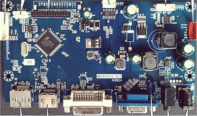
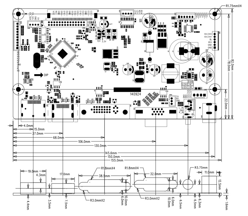
touchscreen

touch

Touch and Displays is the top touchscreen displays provider for higher value industrial display

PRODUCT description

AD / board

모바일 3뎁스 영역

AD / board

AD_BOARD

Board Layout

This Page specified the functions of all the key interface based on physical product.
Detailed Function, refer to Point 7.

Transport, Storage, Usage

• Do not press heavily, bent and transformer
• To prevent from Static and water
• Relative Humidity: ≤80%
• Storage Temperature: -20~+60℃
• Working Temperature:-10~+40℃

   DATA  SHEET  DOWNLOAD SPEC

Specification

  • Version Recorder
    Ver. No. Date Pages Version
    1.0 Oct 21, 2014 All First Version
  • General Description

    This Board is used for TFT LCD Panel applied for LCD Monitor, or Advertising Machine, Or Digital photo frame,support resolution up to WUXGA 1920x1200; WUXGA(1920X1200) dot to dot display, LVDS max output Full HD 1920X1200, Input Analog Signal: R G B for VGA and DVI, display color up to 24bit. Synchronous automatic detection happens when Line frequency is between 30 and 94.5HZ, Field frequency 56HZ to 75HZ. Synchronous mode requires the Synchronous signal of line-field separation.
    It is with audio power amplifying function, output 2Wx2, volume can be adjusted by Pressing key. Also with LED backlight driver, it can drive LED panel not larger than 32inch.

  • Product Specification

    ItemSpecification
    Signal Input VGA: Analog RGB(0.7Vp-p) (TTL)
    DVI:TMDS
    Display Port V1.2 16 bits deep color mode
    HDMI V1.4 Adobe color space
    Support Mode DOS, VGA, SVGA, XGA, SXGA+, UXGA, WXGA, WXGA+, WSXGA, WSXGA+, WUXGA ETC.
    Color 24bit
    Horizontal Frequncy 30-94.5KHz
    Field Frequency 56-75Hz
    Output Dual LVDS Standard
    Audio Output Power 8ohm 2W×2
    Control Key POWER、BRI+、BRI-、AUTO、NENU、LED_R、LED_G
    OSD Menu Brightness, Contrast, Auto, Phase, Clock, Field Position, Function, Reset;
    OSD Language(Option al) Chinese, English, French, Italian, Arabian etc.
    Power Input 24V/12V(+/-0.6V)(DC)
    Power Operation Normal Work Mode
    Size 155mm(L)x82mm(W)x16mm(H)
    Plug & Play Support
    Power Management Standby Power < 1W
  • PC-RGB Support Mode List

    Here lists part of the PC-RGB Mode supported by this Board, including it’s field Frequency, Horizontal frequency, and resolution.
    PC-RGB Mode List( this table only for reference, the actual data might be different from them because of different signal output sources.)

    ModeResolutionLine Frequency
    (KHz)
    Field Frequency
    (Hz)
    Standard
    WUXGA 1920X1200 74.5
    94.0
    60
    75
    -
    UXGA 1600X1200 74.5
    94.0
    60
    75
    VESA
    WSXGA+ 1680X1050 65.2
    82.2
    60
    75
    -
    WXGA+ 1440X900 55.9
    70.5
    60
    75
    -
    WXGA 1280X800 49.7
    62.6
    60
    75
    -
    SXGA+ 1400X1050 65.2
    82.2
    60
    75
    -
    SXGA 1280X1024 63.6
    80.2
    60
    75
    VESA
    XGA 1024X768 47.7
    56.0
    60.1
    60
    70
    75
    VESA
    SVGA 800X600 37.3
    43.8
    47.3
    60
    70
    75
    VESA
    VGA 640X480 29.8
    35.0
    37.7
    60
    70
    75
    VESA
    DOS 640X480
    720X400
    29.8
    29.2
    60
    70
    VESA
  • PCB Size and Structure Specification

    PCB Size :
    ☆ PCB Thickness + Height of top parts = 16.0mm
    ☆ Screw Hole Size: Dia 3.6mm

    Structure
    AD

  • Key Interfaces Definition and Specification
    (Face to indentation of the interface , the 1st Pin is on the left)


    ☆ CN8(6pin/2.0mm)Backlight Power-control interface
    Pin NoDefinitionDescription
    1 24V/12V Backlight Power
    2 24V/12V Backlight Power
    3 BL Backlight On/Off Signal
    4 ADJ Backlight Luminance Adjust signal
    5 GND Ground
    6 GND Ground
  • ☆ CON9(2 X 15PIN/2.0)LVDS Interface
    Pin NoDefinitionDescription
    1 LCD-VDD Power for Panel
    2 LCD-VDD Power for Panel
    3 LCD-VDD Power for Panel
    4 GND Ground
    5 GND Ground
    6 GND Ground
    7 RXO0- LVDS ODD 0 - Signal
    8 RXO0+ LVDS ODD 0 + Signal
    9 RXO1- LVDS ODD 1 - Signal
    10 RXO1+ LVDS ODD 1 + Signal
    11 RXO2- LVDS ODD 2 - Signal
    12 RXO2+ LVDS ODD 2 + Signal
    13 GND Ground
    14 GND Ground
    15 RXOC- LVDS ODD Clock - Signal
    16 RXOC+ LVDS ODD Clock + Signal
    17 RXO3- LVDS ODD 3 - Signal
    18 RXO3+ LVDS ODD 3 + Signal
    19 RXE0- LVDS EVEN 0 - Signal
    20 RXE0+ LVDS EVEN 0 + Signal
    21 RXE1- LVDS EVEN 1 - Signal
    22 RXE1+ LVDS EVEN 1 + Signal
    23 RXE2- LVDS EVEN 2 - Signal
    24 RXE2+ LVDS EVEN 2 + Signal
    25 GND Ground
    26 GND Ground
    27 RXEC- LVDS EVEN Clock - Signal
    28 RXEC+ LVDS EVEN Clock + Signal
    29 RXE3- LVDS EVEN 3 - Signal
    30 RXE3+ LVDS EVEN 3 + Signal
  • ☆CN14(6PIN/2.0mm Rice Yellow):LED Backlight Output
    Pin NoDefinitionDescription
    1 LED-
    2 LED-
    3 LED+
    4 LED+
    5 LED-
    6 LED-
  • ☆CN17(4PIN/2.0 mm Rice Yellow):Loudspeaker output Socket
    Pin NoDefinitionDescription
    1 LO+ Left Channel Loudspeaker Output+
    2 LO- Left Channel Loudspeaker Output-
    3 RO- Right Channel Loudspeaker Output-
    4 RO+ Right Channel Loudspeaker Output+
  • ☆CN22(10PIN/2.0 mm Rice Yellow):Press Key Board Interface
    Pin NoDefinitionDescription
    1 POWER Standby
    2 R Indicator(Red)
    3 G Indicator(Green)
    4 GND Ground
    5 UP + (Volume, Brightness etc.)
    6 DOWN -(Volume, Brightness etc.)
    7 AUTO Auto Adjust / Exit
    8 MENU Menu
    9 EXIT Exit
    10 NC Reservation